
i
(Due to the number of image references this articleis best read via the digital magazine on the link above)
This month’s article is about Jelly. Unfortunately, not the kind that can be served with whipped cream after about four hours in the fridge (sorry) – but instead the video artefact seen from improperly stabilised video cameras.
One of the greatest challenges I face when designing a Special Camera system is how to minimise such vibrations, be they the very passive – such as vibrations from a human wearing a camera system (10 – 20Hz), or more pronounced (try strapping a camera to a race car!).
Many small cameras (including mobile phones) now boast they use Electronic Image Stabilisation (EIS) or Optical Image Stabilisation (OIS) to combat this. In this article, we’ll explore both of the technologies and how picking either one may affect your shoot.
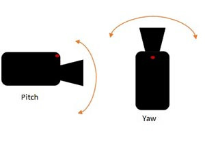
Firstly, Optical Image Stabilisation. OIS uses mechanics in order to perform image stabilisation. This is performed by either shifting the lens, a part of the lens, the sensor – or all of the above. Figure One shows a lens-based OIS implementation. In such an implementation, gyroscopic sensors will feed values measuring lens position in regards to pitch and yaw (as per Figure Two) to a microprocessor. Once the on-board processor has calculated how much displacement has occurred, either magnets or small pouches of fluid are triggered to move the lens in the opposing direction to the movement the camera experienced. In this case, in Figure One, the shifting lens would move up, down, left or right based on this information. This means that the unstable image path entering the lens is compensated for by the motion of the shifting lens, thus meaning the sensor receives a stabilised image.
The alternative approach is to employ EIS, or Electronic Image Stabilising. This method makes no attempt to mechanically stabilise the image, instead relying on in-camera software to interpolate the motion the camera’s gyros have noted, then digitally make corrections based on this.
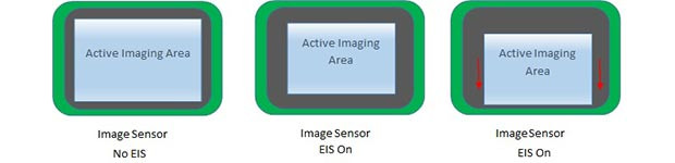
The first picture shows a camera’s sensor running normally, using the full sensor for active imaging. The second cell shows what happens when EIS is turned on – the image becomes cropped to permit some pixels to be used as ‘buffer’ to provide stabilisation. The final cell shows what happens when the gyros detected that the camera’s lens has pitched up – it has compensated by using a lower section of the sensor for the active image, now turning the upper area of the sensor into unused, buffer pixels.
There is no ‘better’ technology – however, I tend to consider a few things before selecting which approach I wish to use.
Firstly, OIS has the disadvantage that systems tend to be slightly larger with a higher cost. If it is expected the camera could be damaged or needs to be kept small, it can sometimes be hard to justify the additional bulk or price for a camera that may only ever be used once! In addition to this, having additional moving elements does, in some cases, reduce how robust the system is.
However, EIS in many cases reduces the overall resolution of the image to provide the needed buffer space for the image stabilisation. Also, as no attempt to stabilise the image has been made, motion blur can sometimes be more pronounced as the image being captured by the sensor is less stable.
For now, it remains a balancing act when it comes to selecting how best to stabilise a camera. Of course, no solution is better than a properly mounted rig – yet I’ll be looking around IBC this year with keen eyes to see how manufacturers have developed on their stabilisation techniques.